
Inside the Flo Hauler: Engineering a 4×4 BLDC Drivetrain for Heavy Construction
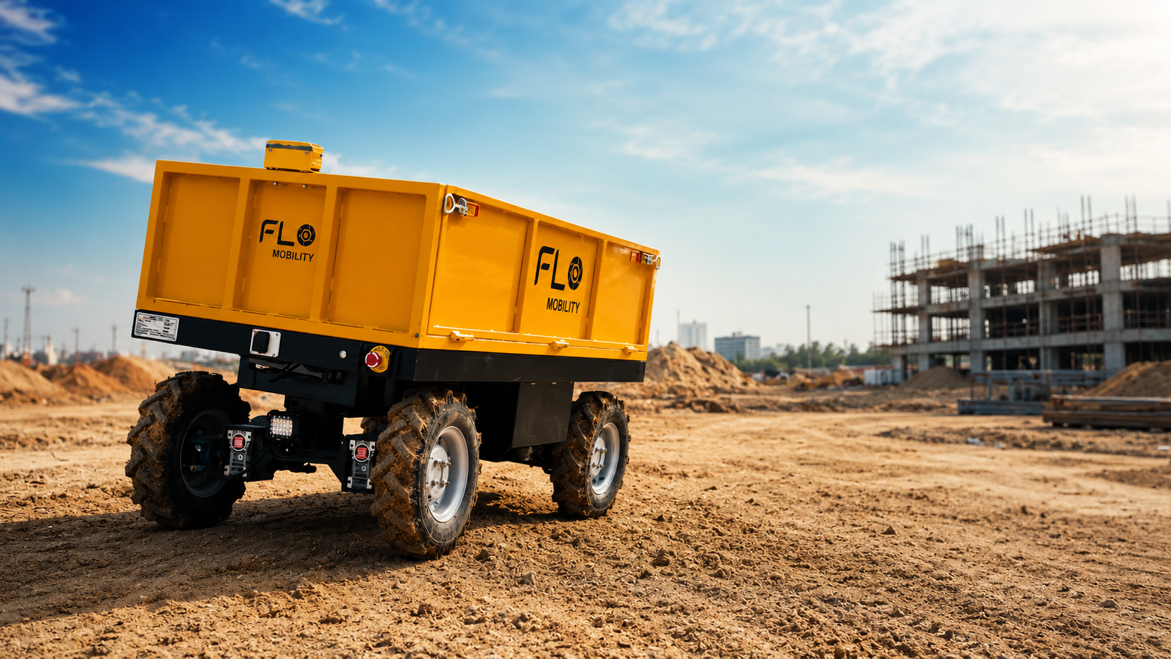
A Robot Has to Move Where the Ground Doesn't Cooperate
A construction site never stays the same.
One moment, the robot is moving smoothly. The next, its wheels hit loose soil. Then comes a slope, an uneven patch, or a wet section with less grip.
For a robot carrying up to 500 kg, these changes are more than just bumps in the road. They put the drivetrain to the test.
Unlike warehouse robots that operate on smooth, predictable floors, construction robots have to work with the terrain they get.
So, what keeps a robot moving when the ground gets difficult?
The answer starts with the drivetrain.
Flo Hauler uses a 4×4 BLDC drivetrain designed to deliver the torque, traction and control needed for autonomous material movement across demanding construction sites. To understand why, it helps to look at the engineering behind each part of the system.
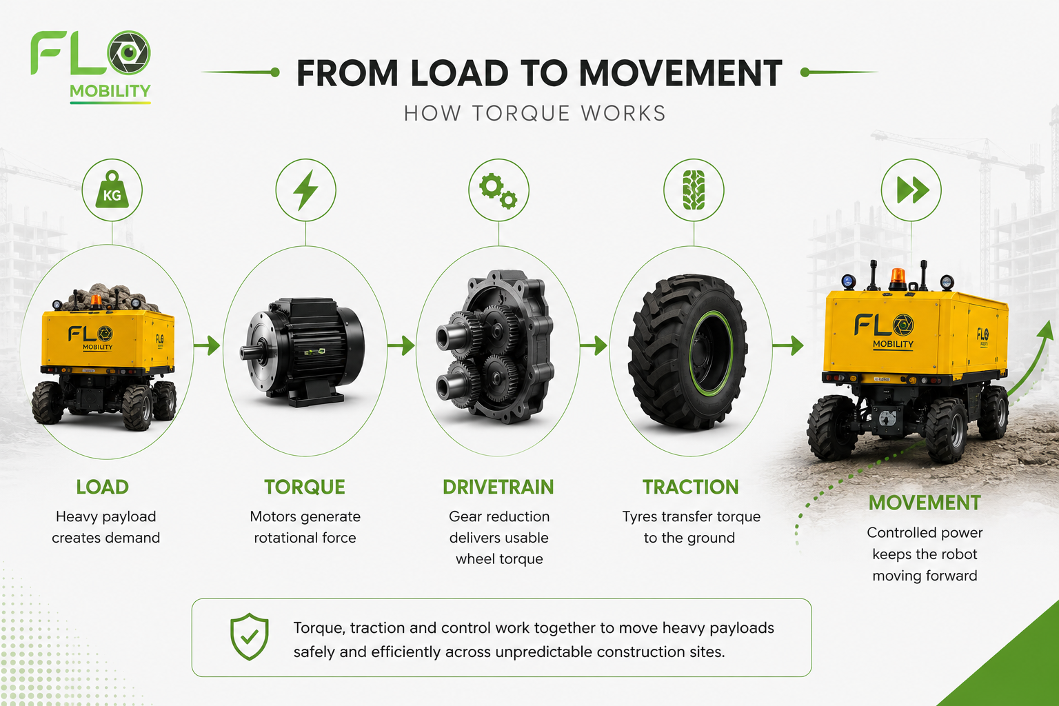
The Real Engineering Challenge: Torque, Traction and Control
Moving a vehicle is one problem.
Moving a heavy payload across unpredictable terrain is another.
For construction material movement, the drivetrain has to solve three connected challenges:
Generate enough torque
Maintain traction
Control how that torque is delivered
Torque is the rotational force that helps a vehicle move, particularly when it is carrying a heavy load or climbing a gradient.
But producing torque is only part of the equation.
The wheels also need enough grip to transfer that torque to the ground. When the surface changes from firm soil to loose material or a wet patch, the available traction can change as well.
This makes drivetrain performance a system-level engineering problem, rather than simply a question of motor power.
Why BLDC Motors?
What Is a BLDC Motor?
BLDC stands for Brushless Direct Current motor.
Unlike conventional brushed DC motors, BLDC motors use electronic commutation instead of mechanical brushes and a commutator to control current switching.
This makes them well suited to applications such as electric mobility and robotics, where efficiency, controllability and reliable operation are important.
But for Flo Hauler, choosing BLDC motors was not simply about choosing a modern motor technology.
The selection was driven by the demands of the application.
Why Efficiency and Torque Matter
Flo Hauler uses four 500 W BLDC motors, with a specified motor torque of 100 Nm and an operating speed of approximately 60–70 RPM.
The objective is not high-speed travel.
It is controlled, dependable propulsion for a robot designed to move material across a construction site while carrying a substantial payload.
In this application, torque matters more than simply achieving high rotational speed.
The motor needs to provide the foundation for moving the vehicle and its payload, while the rest of the drivetrain converts and controls that output for the terrain.
Why the Motors Don't Drive the Wheels Directly
A motor's speed and torque characteristics are not necessarily the same characteristics required at the wheel.
This is where gear reduction becomes important.
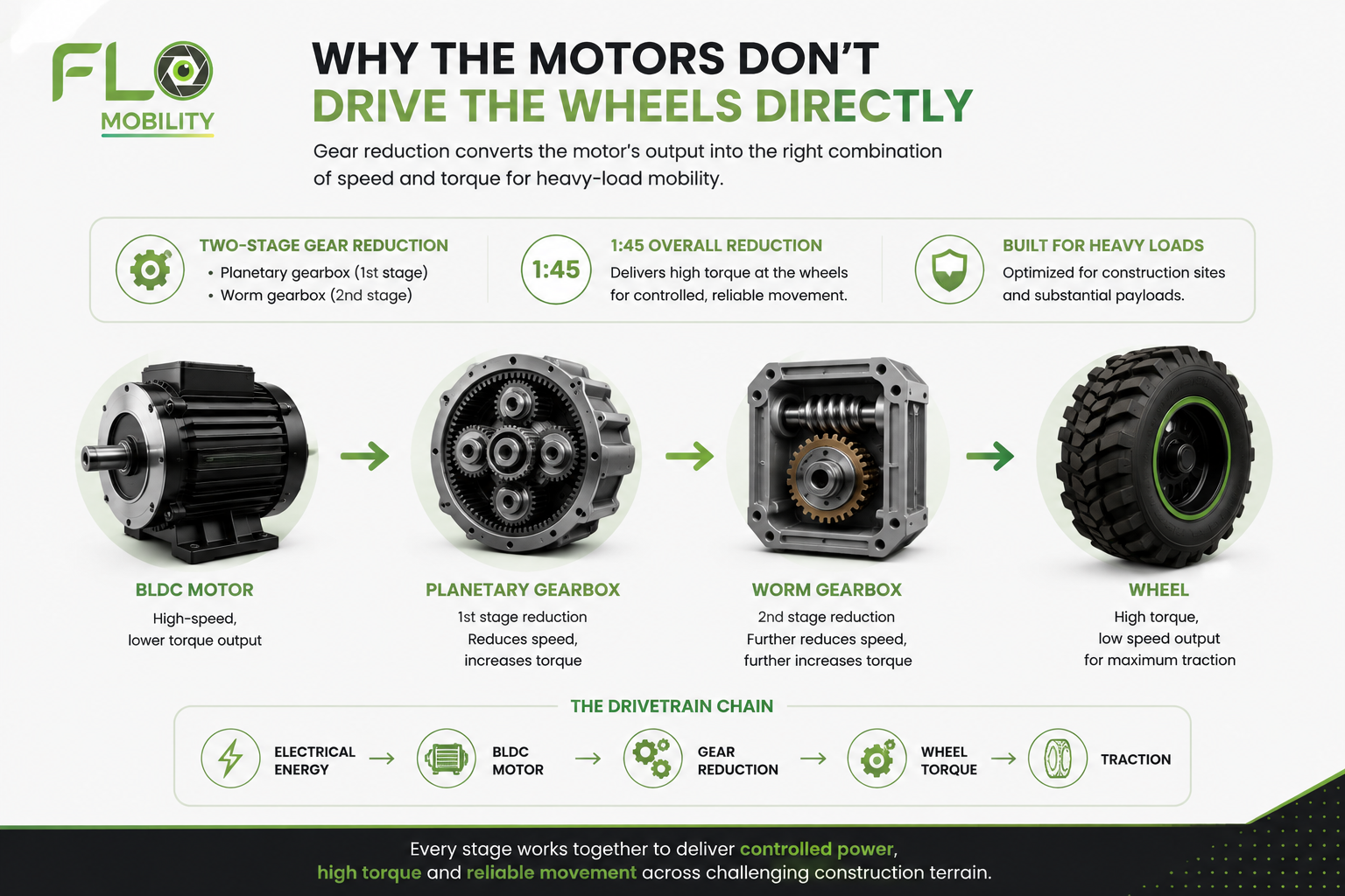
Flo Hauler uses a two-stage gear reduction system:
Planetary gearbox as the first stage
Worm gearbox as the second stage
1:45 overall gear reduction
The gear reduction transforms the motor's rotational output into a more suitable combination of speed and usable wheel torque for heavy-load mobility.
The drivetrain can therefore be understood as a chain:
Electrical energy → BLDC motor → Gear reduction → Wheel torque → Traction
This is why motor power alone does not tell the complete story.
The motor, gearbox, wheel and control system have to work together as one drivetrain.
How the Planetary and Worm Gearboxes Work Together
The planetary gearbox forms the first reduction stage, followed by the worm gearbox.
Together, the two stages provide the specified 1:45 overall gear reduction, helping convert motor output into the wheel-level characteristics required for the vehicle.
Why 4×4 Matters on a Construction Site
Construction sites rarely provide identical ground conditions beneath all four wheels.
One wheel may be travelling over firm ground while another encounters loose soil or a wet section.
Flo Hauler uses a 4×4 drivetrain, with all four wheels powered by independently controlled BLDC motors.
This gives the vehicle four powered contact points through which torque can be transferred to the ground.
But four motors alone do not make a capable 4×4 system.
The way those motors are controlled is just as important.
Why Four Driven Wheels Matter
A 4×4 architecture allows the drivetrain to work through all four wheels instead of relying on a single driven axle.
For construction robotics, this becomes particularly relevant when terrain and payload conditions change during a material movement trip.
The objective is not simply to have four motors.
It is to coordinate them so that available torque can be used effectively.
FOC: Coordinating Four Motors
Each of Flo Hauler's four BLDC motors is independently controlled using Field-Oriented Control (FOC).
FOC is an electronic motor-control technique that enables precise control of motor behaviour by controlling the electromagnetic fields responsible for producing torque.
At the vehicle level, the Vehicle Control Unit (VCU) manages torque distribution across the four wheels. The VCU also handles the relevant differential and steering control strategy.
This creates a layered control architecture:
BLDC motors provide the electrical-to-mechanical drive.
FOC motor controllers regulate individual motor behaviour.
VCU coordinates the four motors and manages torque distribution.
Wheels and tyres convert that controlled output into traction at the ground.
The result is a coordinated drivetrain rather than simply four separate motors.
What Happens When a Wheel Loses Traction?
Imagine one wheel moving from firm ground onto loose or wet soil.
The available grip can decrease.
Simply asking that wheel for more torque may increase wheel spin rather than forward movement.
This is where traction control becomes important.
When reduced traction is detected, the traction-control strategy can increase torque at the other wheels to help the vehicle move out of the condition.
In other words, the drivetrain is not only asking:
"How much torque can we produce?"
It is also asking:
"Where can that torque be used most effectively?"
That distinction matters for autonomous material movement because the vehicle needs to respond to changing site conditions without relying on constant manual intervention.
When Payload Meets a Slope
A gradient adds another layer of demand to the drivetrain.
As the vehicle climbs, the drivetrain has to overcome additional resistance from gravity. With a payload onboard, that demand increases further.
Flo Hauler is specified to climb a 12° gradient with a full 500 kg payload.
Without payload, the specified maximum gradient is 20°.
These figures are system-level outcomes.
Motor torque, gear reduction, four-wheel drive, motor control and vehicle-level torque management all contribute to the vehicle's ability to handle a gradient.
Gradeability, therefore, is not simply a motor specification.
It reflects how the complete drivetrain and vehicle architecture work together.
Why Payload Changes Gradeability
The difference between the specified 12° gradient with a 500 kg payload and 20° without payload illustrates how payload changes the demand placed on the complete mobility system.
As payload increases, the drivetrain has to overcome greater resistance to maintain controlled movement, particularly while climbing.
Ground Clearance: The Mechanical Side of Terrain Capability
Not every terrain challenge is solved through electronics.
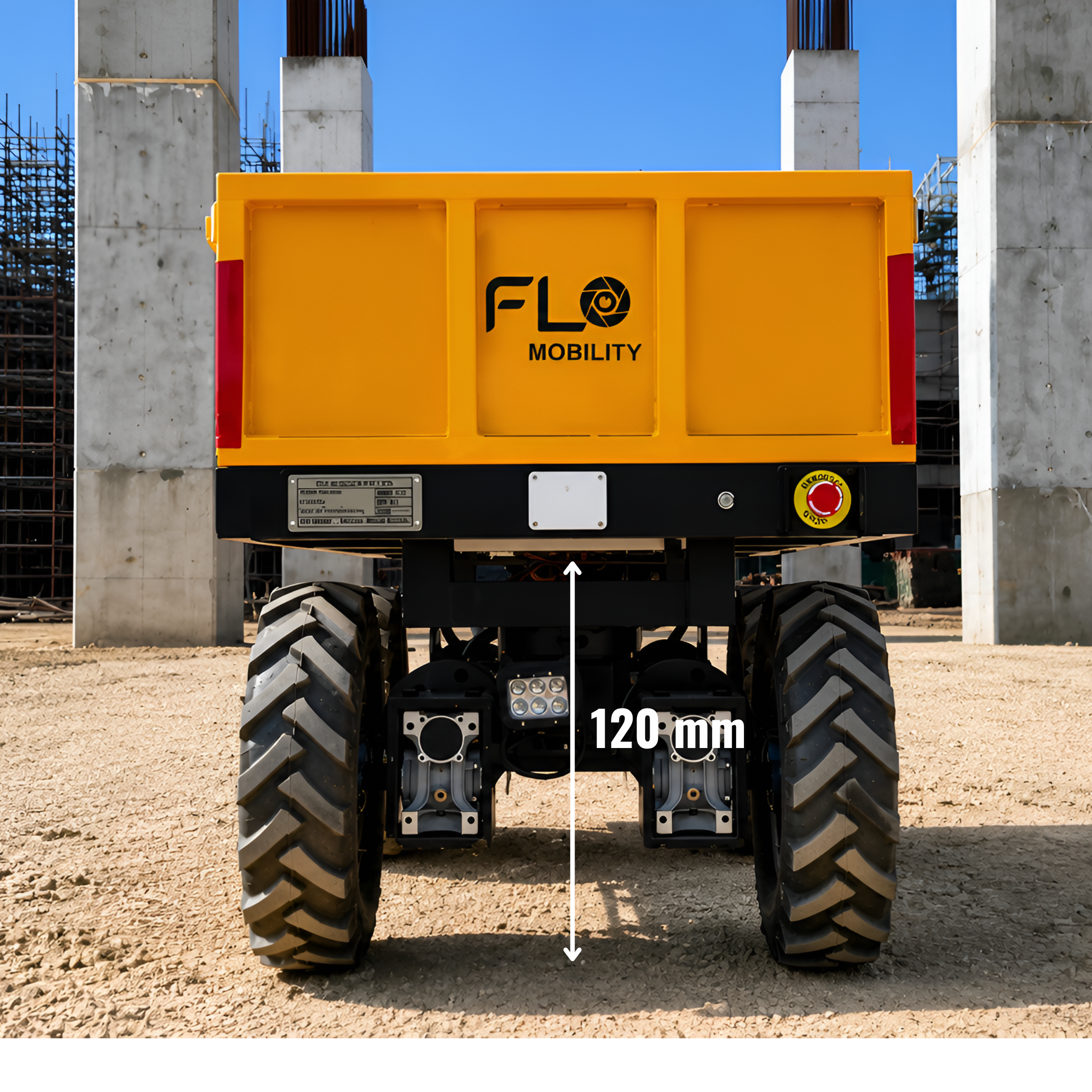
Flo Hauler has 120 mm of ground clearance, providing additional separation between the lower vehicle structure and the surface when travelling over uneven terrain.
Ground clearance does not create torque or traction, but it is another important part of vehicle architecture when designing for construction sites.
Together, the drivetrain, control electronics, wheels, vehicle geometry and payload determine how the robot interacts with the terrain.
Why Ground Clearance Matters on Construction Sites
Construction surfaces can contain uneven sections, changes in elevation and surface irregularities.
Ground clearance is therefore one of the mechanical considerations that complements the drivetrain and control system when designing a robot for real construction environments.
Autonomy Needs Hardware That Can Execute the Plan
Autonomous construction robotics is often discussed through perception, navigation and obstacle avoidance.
These systems help the robot understand its surroundings and determine where it should move.
But software can only command movement.
The hardware has to execute it.
If the navigation system tells the robot to move forward, the drivetrain must generate the required torque, distribute it appropriately and maintain controlled wheel behaviour as the terrain changes.
That is why drivetrain engineering is an important part of autonomous material movement.
Perception determines what the robot sees.
Planning determines where it should go.
The drivetrain makes the physical movement possible.
The Relationship Between Autonomy and Drivetrain Control
A robot can have sophisticated navigation and perception systems, but those systems ultimately depend on the physical platform being capable of executing their commands.
The drivetrain is therefore not an isolated mechanical subsystem.
It is part of the broader autonomy stack that connects a robot's digital decision-making with physical movement.
Engineering for the Construction Site That Actually Exists
Construction sites do not offer ideal operating conditions.
The surface changes.
The gradient changes.
Traction changes.
The payload changes.
The robot still has to perform.
That is why Flo Hauler brings several engineering decisions together:
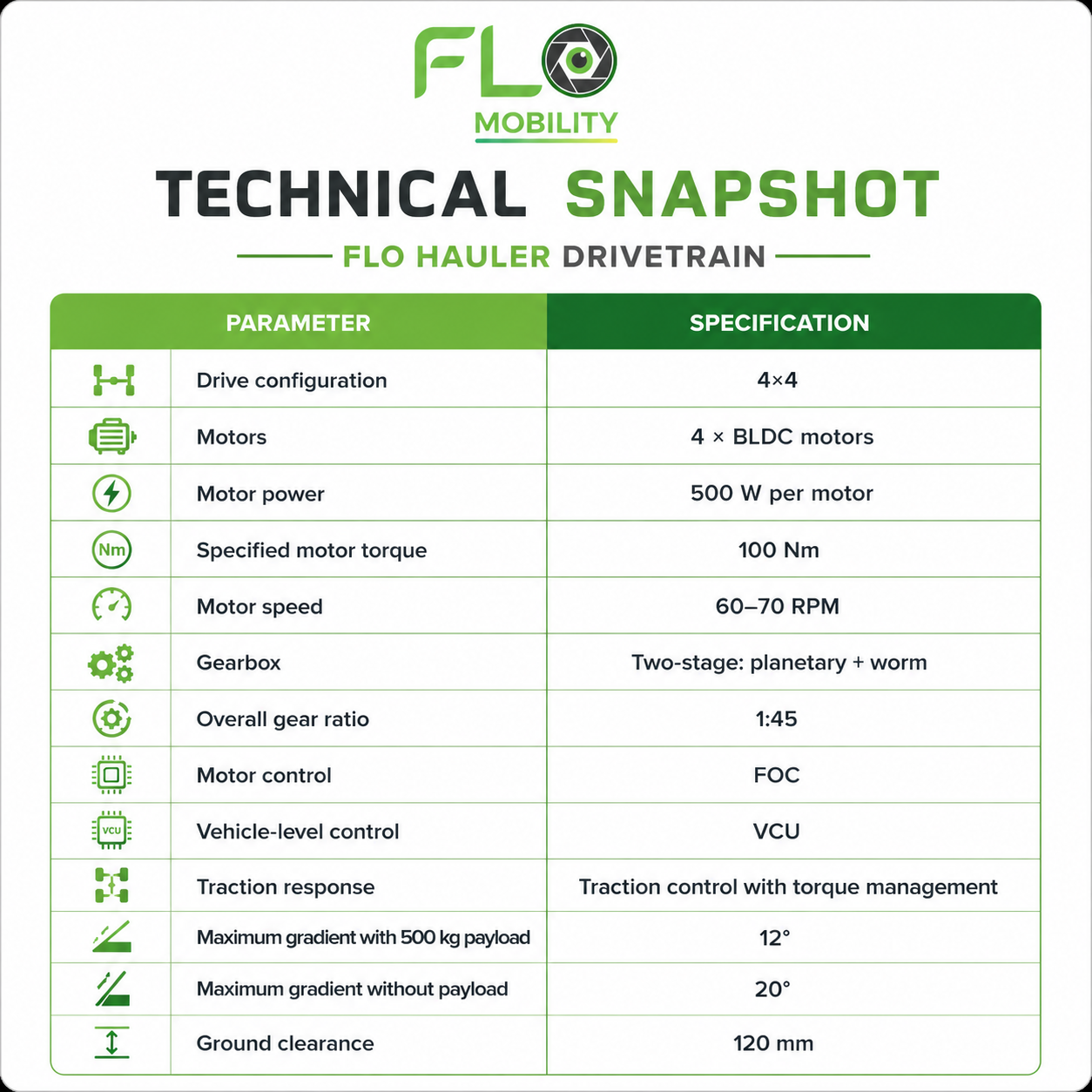
4 × 500 W BLDC motors
100 Nm specified motor torque
60–70 RPM operating speed
Two-stage planetary + worm gearbox
1:45 overall gear reduction
FOC-based individual motor control
VCU-based torque management
4×4 drivetrain
Traction control
12° gradeability with 500 kg payload
20° maximum gradient without payload
120 mm ground clearance
None of these specifications exists in isolation.
Together, they form a drivetrain designed around the realities of construction material movement.
Because construction robotics is not simply about teaching a machine where to go.
It is about engineering the hardware that allows it to get there reliably.
Technical Snapshot: Flo Hauler Drivetrain
Built for Real Construction Sites.
Construction sites are unpredictable-and material movement shouldn’t be limited by the terrain.
With 4×4 BLDC motors, intelligent torque control and a purpose-built drivetrain, Flo Hauler is engineered to move materials reliably across challenging site conditions.
See how Flo Hauler is redefining autonomous material movement. →